Instrument Overview
SoloHI will perform remote observations of the Thomson-scattered white light from the solar wind plasma of the outer corona. It is a single, white-light telescope of 20° half angle with the inner limit of the FOV at an elongation of 5° from the Sun center. The objective lens has a 40° FOV and images the solar wind onto a mosaic of four CMOS Active Pixel Sensor (APS) detector die with an effective total area of 3968 × 3968 pixels.
As the Solar Orbiter approaches the Sun, the spatial resolution will increase relative to the resolution at 1 AU, and the absolute FOV correspondingly will decrease relative to 1 AU. At perihelion, the SoloHI will have the same effective resolution as the SOHO LASCO/C2 coronagraph with a larger FOV (6–60 R⊙) than the LASCO/C3 coronagraph and a higher signal-to-noise ratio (S/N) than C3.
The key design aspects of SoloHI are to reject light from the solar disk to see the faint coronal signal with a good S/N. The SoloHI baffles are designed to minimize the stray light entering the entrance aperture from various sources. For the Solar Orbiter mission, there is a significant complexity – the solar light is reflected by the solar array at the rear of the spacecraft onto the backs of the instrument baffles.
Table 1 gives a summary of the key instrument parameters. The parameters are measured or computed and indicated with an (M) or (C). In order to meet the S/N requirement discussed above for the electron scattered component, a number of single exposures must be taken and summed on board. We refer to these as single and summed images. The exposure time of the single image and the number of single images necessary to be summed for the image are our best estimates and could change in flight.
| Parameter |
Value (M)easured (C)alculated |
| SIM mass | 15.18 kg (M) |
| SPS mass | 1.38 kg (M) |
| Volume |
66.0 XSIM × 40.5 ZSIM × 29.1 YSIM (M) (Door Closed) × 50.8 YSIM (M) (Door Open) |
| Power | 13.5 (w) (average) |
| Telemetry | 53.2 Gbits/Orbit |
| FOV | 40° ×40° square limited to 48° at the detector corners |
| Image array | 3968 × 3968 Pixels (M); Note: Left 10 columns and bottom 10 rows of each die are opaque |
| Boresight direction |
Nominal: 25° from Sun center Measured: 25° 7′26.3″ |
| Angular range |
5°–45° from Sun centre 5.25 R⊙–47.25 R⊙ at 0.28 AU |
| Angular resolution |
36.7 arcsec (Full) 73.5 arcsec (2 × 2 bin); 10.3 arcsec (Full) 20.6 arcsec (2 × 2 bin) equivalent at 0.28 AU |
| Spectral bandpass | 500–850 nm (M) |
| Exposure time per image | Nominal 30 s (C); Range 0.1–65 s (M) |
| Number of summed images | Varies from 1–30 (C) depending on the observing program, heliocentric distance |
Table 1: SoloHI instrument parameters.
SoloHI is comprised of the SoloHI Instrument Module (SIM) and the SoloHI Power System box (SPS). The SoloHI functional block diagram, Figure 1, shows the components of the SIM and SPS. An interconnect harness (not shown) connects the SIM and the SPS, and a spacecraft harness (not shown) connects SoloHI to the spacecraft.
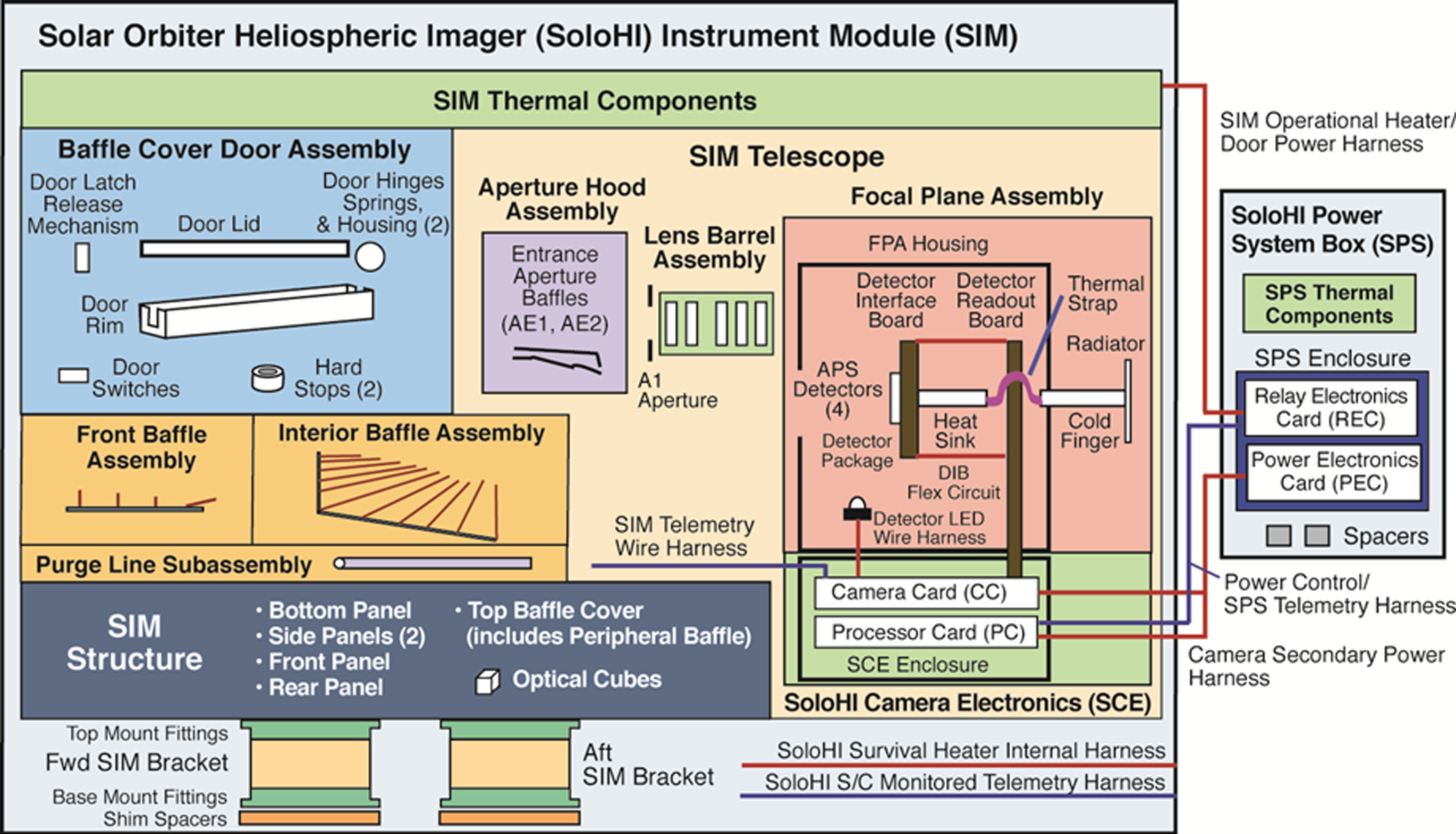
Figure 1: SoloHI functional block diagram.
Both SoloHI instrument units, the SIM and the SPS are mounted on the exterior of the Solar Orbiter +Y panel. The SPS is located underneath the SIM and between the forward and aft SIM brackets that support the SIM. Figure 2 (top) shows the orientation of SoloHI with respect to the Solar Orbiter. The origin of the SIM physical reference frame is located at the center of the aft SIM rigid instrument mount projected down to the base of the aft SIM bracket at the SIM mounting interface plane with the spacecraft deck. The XSIM axis points toward the Sun in its nominal orientation for science observations.
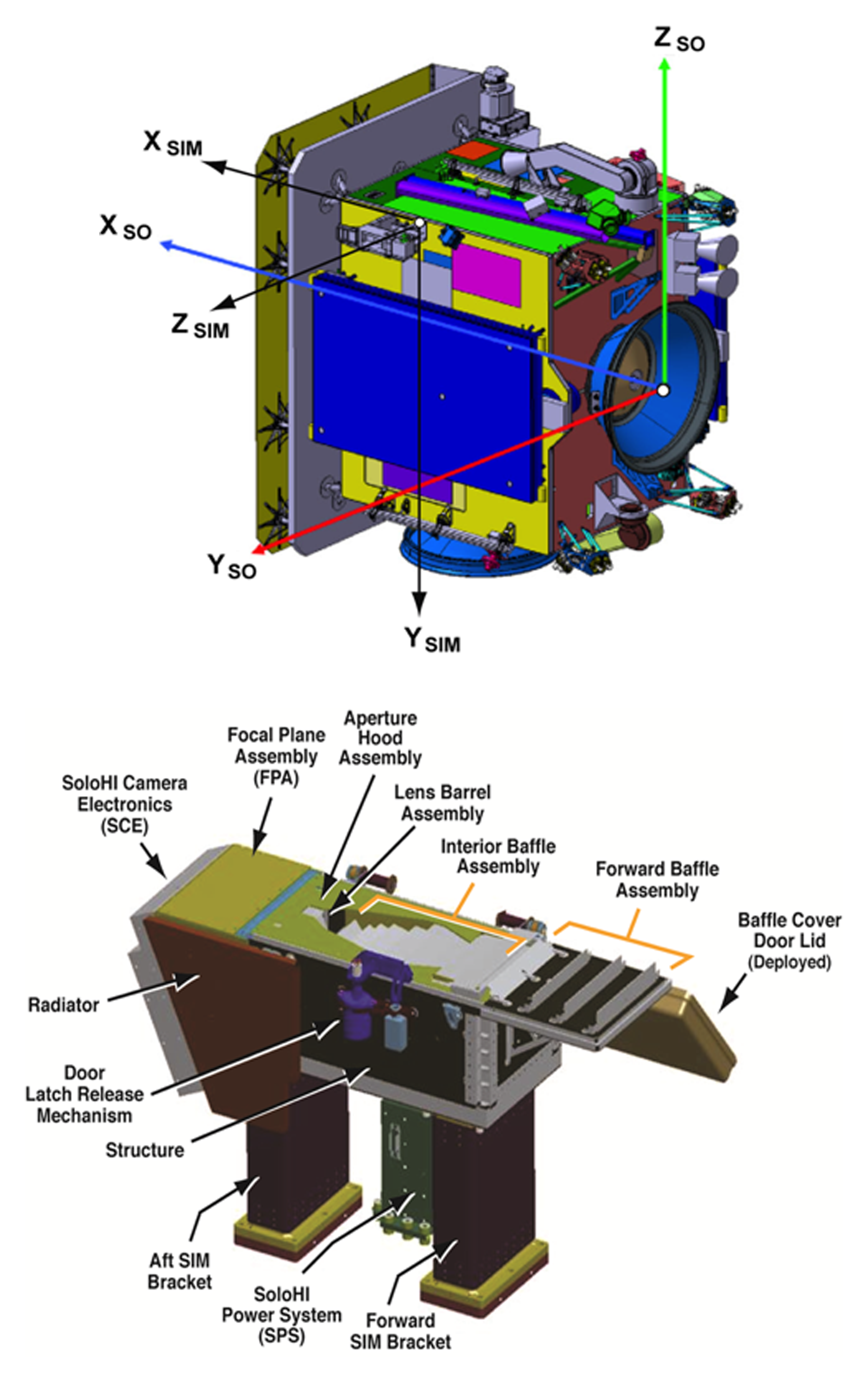
Figure 2: Top: SoloHI accommodation on the Solar Orbiter spacecraft and reference systems. The SIM physical reference frame (subscripts SIM) with respect to the Solar Orbiter mechanical reference frame (subscripts SO). Bottom: SIM and SPS and subassemblies.
The SIM (Figure 2, bottom) includes the structure, the baffle assemblies (forward, interior, peripheral, and entrance aperture baffles), the telescope, the SoloHI camera electronics (SCE), the baffle cover door assembly, the SIM thermal components, and the forward and aft SIM brackets. The SoloHI telescope is composed of the aperture hood assembly, the lens barrel assembly, the focal plane assembly (FPA), and SCE. The SCE is composed of the processor card (PC), the camera electronics card (CC), and the SCE enclosure. The SPS includes the relay electronics card (REC), the power electronics card (PEC), the SPS enclosure, and the SPS thermal components. The SPS receives raw power from the spacecraft and, if commanded, filters it and transforms it to the various voltages required by the SIM. The instrument telescope design is monolithic, with no moving parts.
Solar Orbiter provides operational power to the SPS and survival power to the SoloHI survival heaters on the SIM and SPS. In addition, Solar Orbiter forwards instrument commands to the CC and receives science data and housekeeping telemetry over the SpaceWire interface. Each pixel of the APS detector converts the photoelectric charge to volts, which is digitized off-chip, and the signal is transferred to the SCE. The pixel readout rate is 2 Mpixels s−1, and the image data is processed and then sent to the spacecraft for storage on the solid-state mass memory (SSMM) for later transmission to the ground. The APS is cooled passively by a radiator mounted on the side of the SIM with a view to deep space.