SoloHI Instrument Design
1. Optical design
The SoloHI telescope has a relatively simple design with a single lens assembly which, together with the detector forms the FPA. For SoloHI, direct illumination from the Sun is blocked by the heat shield. The baffles are designed to minimize the stray light entering the entrance aperture from various sources. The heat shield, one RPW antenna, and the solar array all either diffract or reflect light onto the instrument.
| FOV | 40° ×40°, limited to 48° in the detector corners |
| Number of lenses | 5 elements |
| Aperture | 16 mm × 16 mm square with rounded corners 19 mm |
| Imaging area (measured) | 38.84 mm transverse×40.12 mm radial |
| Focal length (theoretical) | 55.9 mm |
| Plate scale (theoretical) |
0.971 mm deg−1 at 0° field; 1.082 mm deg−1 at 20° field |
| F/# (theoretical) | 3.48 |
| Spectral range (measured) | 500 nm–850 nm |
| Resolution (measured) | 1.3′ [arcmin] at full detector resolution. |
| Boresight/nominal pointing | 25° elongation from the Sun centre |
| Inner FOV cutoff (measured) | 5.4° fully vignettes; 9.30° fully unvignetted |
Table 1: Optical design parameters.
2. Lens barrel assembly
The SoloHI lens barrel assembly has a five-element wide-angle design and was fabricated by Jenoptik Optical Systems Inc. The lens design was optimized to maintain optical performance over the large 40° FOV and minimize stray light from scattering. A summary of the SoloHI optical parameters is shown in Table 1. Thermal and radiation requirements were incorporated into the design. Figure 1 shows the lens layout and ray tracing. The resolution is optimized for the 7.5° field angle, to satisfy the science requirement for observing shocks, or density power spectrum in the corona or SIR boundaries. The bandpass is set by using a long and short wavelength cutoff filter deposited on lens surfaces 7 and 9, respectively.
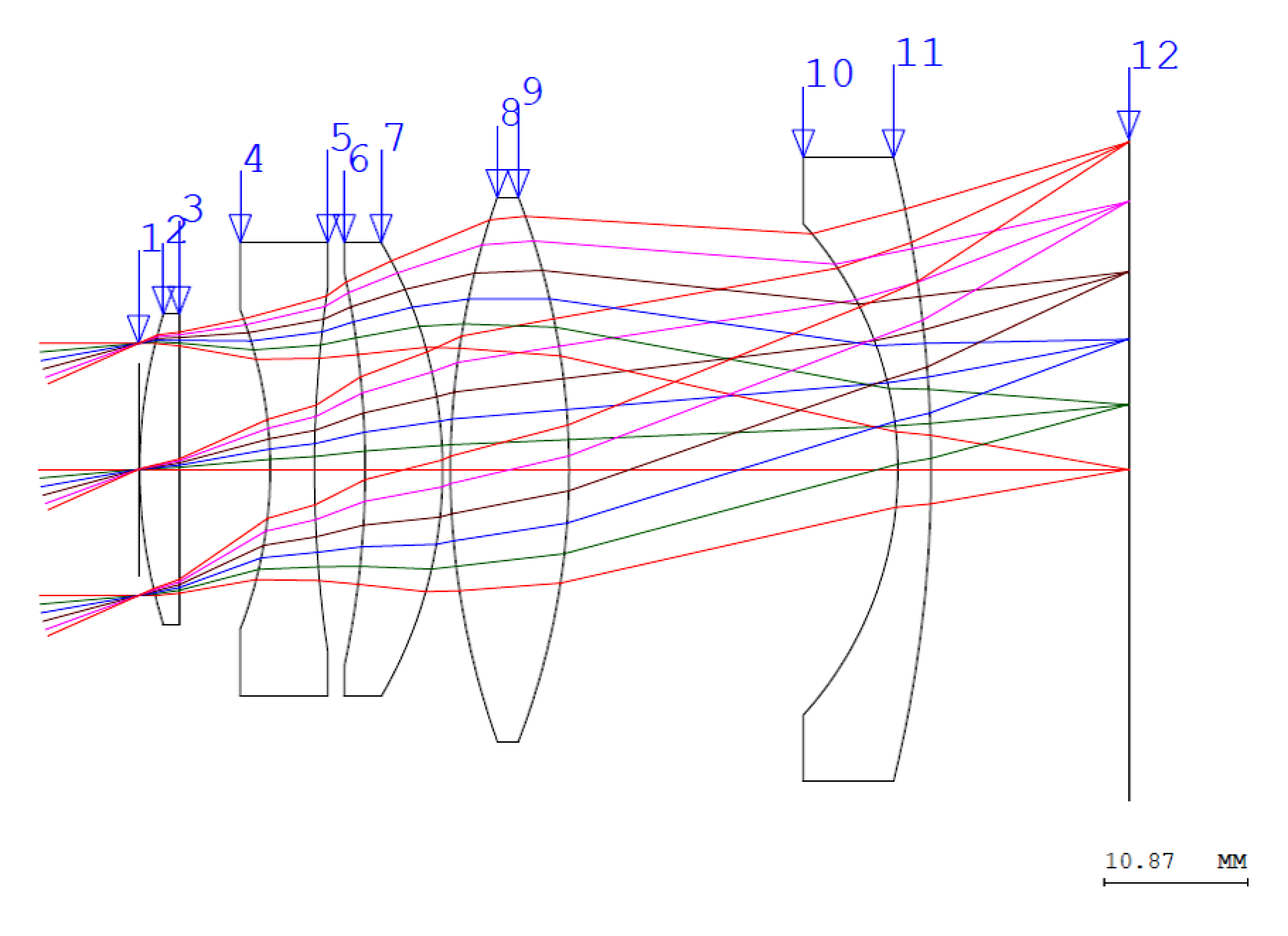
Figure 1: Lens element layout and ray tracing. The lens surfaces are indicated by the number along the top for the five elements. Surfaces 1 and 12 are the front lens plane and the focal plane, respectively.
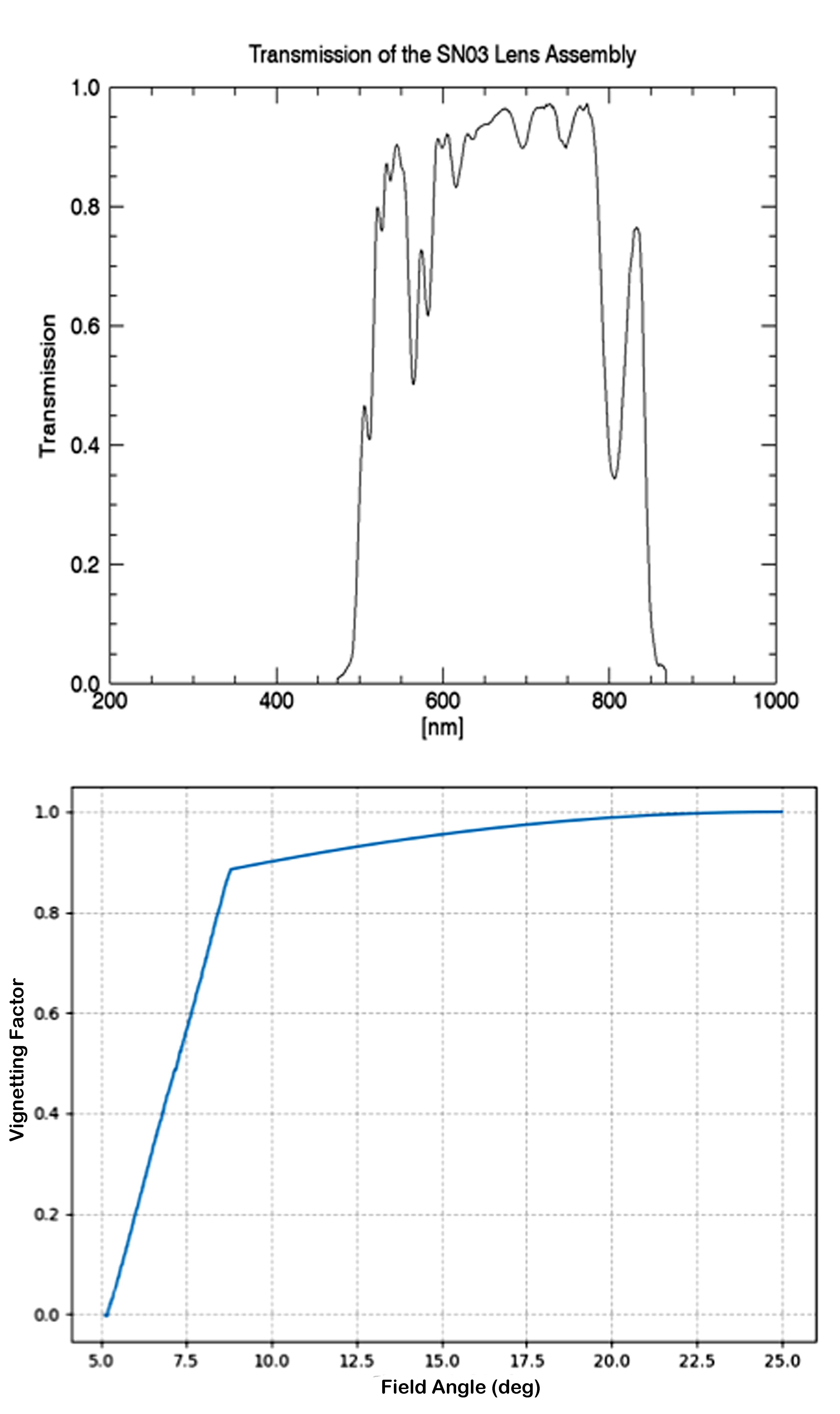
Figure 2: Top: bandpass of the flight lens (SN03), measured by Jenoptik. The bandpass is defined by a combination of short-pass and long-pass coatings applied to surfaces 7 and 9. Bottom: vignetting factor vs. the field angle, from the inner FOV edge (5.4°) to the boresight (25°). The inner FOV is vignetted by the forward baffles from 5.4° to 8.8° and follows a cos3θ law.
The top panel of Figure 2 shows a plot of the measured bandpass of the flight lens assembly. The other lens surfaces are coated with an anti-reflective coating to maximize the throughput and minimize ghosting. The bandpass from 500 to 850 nm is wider than SECCHI/HI-1 which was from 630 to 730 nm. This difference enables SoloHI to gather significantly more photons than SECCHI/HI-1. SECCHI/HI-1 had the same bandpass as the SECCHI/COR2 to ensure that they would have the same photometry so that structures could be better followed from COR2 into HI-1. Due to the presence of the forward baffles, whose function is described in the following section, the image is vignetted all along the inner edge of the FOV, from approximately 5.4° elongation to 9°. The profile of the vignetting is shown in the bottom panel of Figure 2, from the theoretical boresight (25° elongation from the Sun centre) to the inner edge (5° elongation). Natural vignetting of the lens is also present and follows a cosine3 law with the field angle.
3. Stray-light rejection
Baffle definition and position. There are four sets of baffles – each serving a specific purpose.
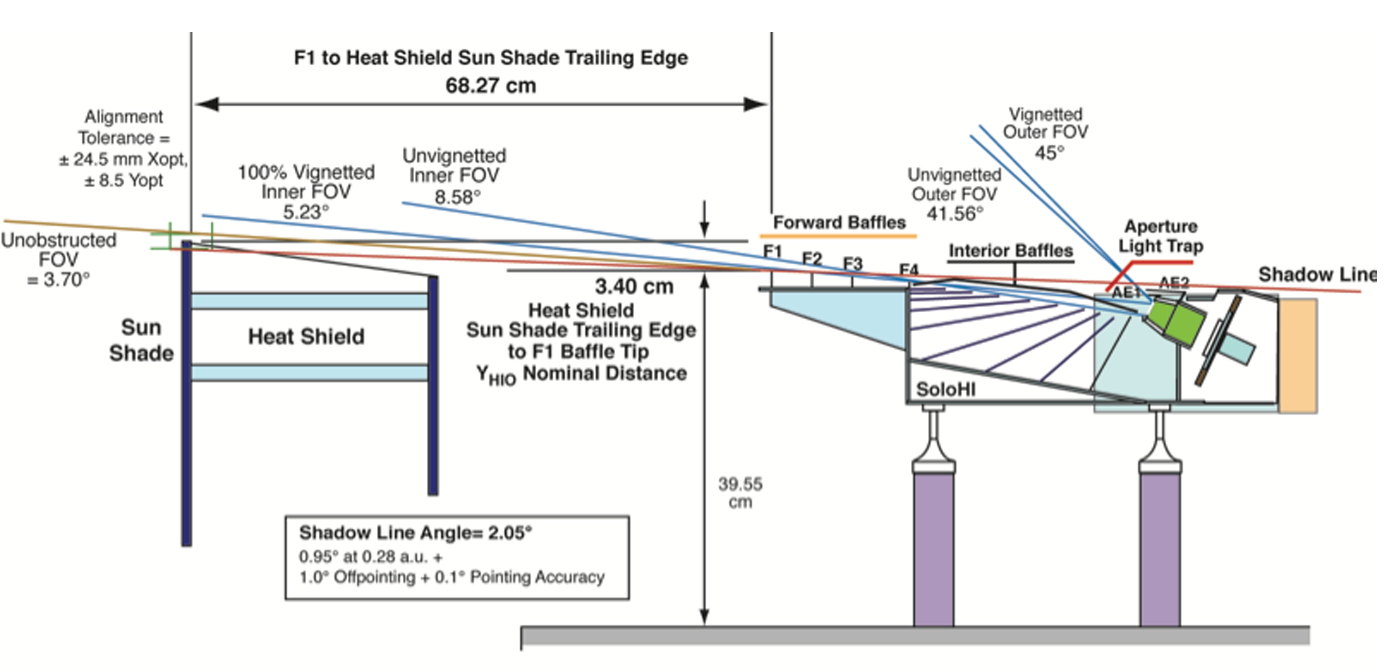
Figure 3: Definition and position of the optical baffles, with respect to the SIM and spacecraft heat shield.
-
Forward baffles: a set of five baffles, labeled F1, F2, F3, F4, and I0 in Figure 3, which block the direct and reflected sunlight and the diffracted light from entering the telescope entrance aperture. The edge of the spacecraft heat shield (HS) is the first baffle in the system. Using the HS as the first baffle imposed requirements on the position of F1 relative to the HS, and also the angle between the F1 and F2 relative to the angle to the HS edge. The I0 baffle is not labeled in the figure but is the dark horizontal line just after the F4 vertical baffle.
-
Interior baffles: a set of nine baffles each pointing to the light trap. The telescope aperture only sees the bottom surface of these baffles, meaning that any stray-light source above the SIM will have to bounce twice before entering the telescope aperture, thereby increasing the rejection of the stray-light source.
-
Aperture light trap: a set of two baffles, labeled AE1 and AE2, in Figure 3. Their role is to trap the residual diffracted sunlight coming from F4 and the reflected stray light coming from the top of the interior baffles.
-
Peripheral baffle: not shown in Figure 3, the peripheral baffle is a plane that goes on top of the interior baffles. It cuts into the FOV of the telescope, blocking the direct view of the telescope aperture of the spacecraft heat shield.
Diffracted stray light. The design of the forward baffles (Figure 3) is based on the SECCHI/HI baffle design (Socker et al. 2000; Halain et al. 2011), however in this case the edge of the spacecraft heat shield is used as the first baffle, and then four baffles on the SoloHI, that is, HS, F1, F2, and F3, reduce the diffraction from that first edge to an acceptable level.
4. Mechanical design
SoloHI adopted a modified proto-flight model (PFM) philosophy, meaning that there was no qualification model (QM) of the full instrument. A QM was used to ensure the design of the focal plane assembly, which went through two iterations before the vibration and thermal requirements were satisfied. The flight instrument was vibrated to qualification levels for flight durations. The mechanical assembly of the SoloHI instrument has the following components. More details on these can be found in Howard et al. (2020).
1. Instrument enclosure
2. Focal plane assembly
3. Baffles
4. Door
5. Instrument mounts
5. Electrical design
The SoloHI electrical design (Figure 4) consists of four subsystems: the SoloHI Power System (SPS), the SoloHI Camera Electronics (SCE), the Detector Readout Board (DRB), and the Detector Interface Board (DIB). Each component comprises several subsystems, which are briefly described below.
5.1. SoloHI Power System
The SPS receives the power on and off commands from the spacecraft which open and close the relays on the relay electronics card (REC), respectively. The SPS also receives raw operational power from the spacecraft and if commanded via the relays on the REC, filters this power on the power electronics card (PEC), and transforms it to the voltages, +3.3V, and filtered ±5V, which are required by the SIM.
5.2. Processor Card
The SoloHI PC controls the operation of the instrument by hosting the scheduling of images by commanding the camera at the appropriate times and commanding the image processing tasks to be performed either by the camera or on its own processor. The PC also controls the commands to open the door and the operational heaters. There is a lot of interaction between the processor card (PC) and the camera electronics card (CC).
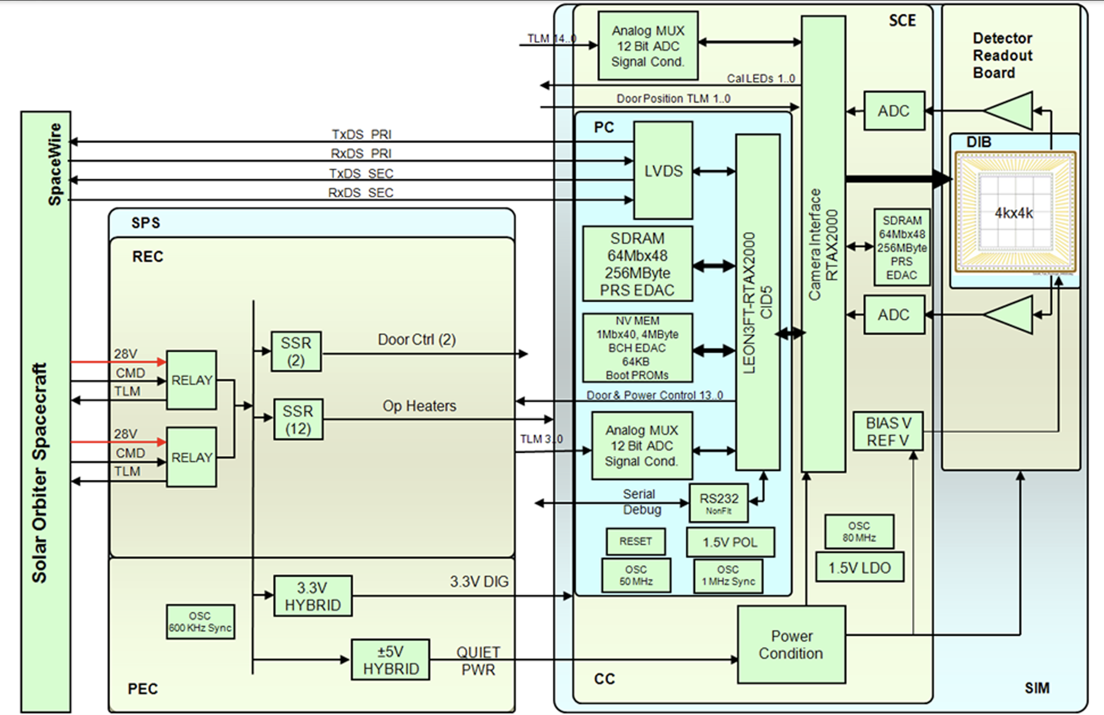
Figure 4: SoloHI electrical block diagram. The SPS contains two cards – the PEC and the REC. The SCE contains two cards – the CC and the PC.
5.3. Camera Card
The CC receives the parameters for image acquisition (single or summed exposures) and the various simple image processing tasks. It returns the image to the PC and loads a register containing the header information collected by the CC, which is read by the PC.
5.4. Detector interface and readout boards
The DIB/DRB provides the electrical interface between the Active Pixel Sensor (APS) and the CC. The four APS detector die are mounted to the DIB, which interfaces through a rigid-flex cable to the DRB. Where possible, printed circuit traces on the DIB combine the same signals from the four die, into a single signal onto the rigid-flex cable. This greatly reduces the number of wires in the rigid-flex cable and also reduces the heat transfer from the DRB to the APS. The DRB multiplexes the various video outputs from the APS and conditions the video signals to match the requirement for the ADC on the CC.
6. Active Pixel Sensor
The SoloHI detector is a mosaic of four APS die, each of 2048 columns and 1920 rows. The die are two-side buttable and are mosaiced in a pinwheel fashion to form the SoloHI detector, with an image size of 3968 × 3968 pixels. We note that the pinwheel configuration is a consequence of the two-side buttable design. The mosaiced device is one of the largest format APS detectors to be fully qualified for space. The APS 5T pixel design and device architecture were developed to meet the Solar Orbiter mission requirements and SoloHI photometric and imaging requirements. Details of the APS architecture and development are documented in Janesick et al. (2010, 2013) and Korendyke et al. (2013).

Figure 5: Schematic of the orientation of the APS with respect to the instrument FOV. Each die is oriented in a pinwheel configuration. The red lines on the corners of each die show the locations of the ten rows and ten columns that are covered with an opaque metal coating. The ground processing software combines the separate images from each die into a single mosaic of the full SoloHI image.
Figure 5 is a schematic that shows the pinwheel configuration of the four die in the mosaic. The solar disk would be to the right and the increasing heliocentric distance would be from right to left. The die positions are numbered 1 to 4 in a counterclockwise direction, beginning on the lower right. The horizontal and vertical lines show the direction of the rows of each of the directions. The red lines at the outer edges of each die indicate the locations of the ten opaque rows and columns. The opaque pixels enable a determination of the bias voltage and dark signal in each exposure. The corner between those lines is the (0,0) pixel. Putting that pixel to the lower left, readout occurs from that pixel along the bottom to the right. The optical system FOV is the circle around the die.
7. Thermal design
SoloHI (SIM and SPS) has an isolated thermal interface with the spacecraft and is designed to be insensitive to temperature changes at the spacecraft mounting interface and its external environment. The conductive flux with the spacecraft shall be between −1 W and +1 W (a maximum of 1 W will flow from the spacecraft to the isolated payload in the cold survival case and a maximum of 1 W will flow from the isolated payload to the spacecraft in the hot survival case).
When SoloHI is operating, the SIM is completely in the shadow of the Solar Orbiter heat shield even at the worst extreme 1.0° off-pointing from the Sun centre at orbital perihelion, and therefore there is no direct solar load. The SoloHI instrument has been designed to operate and continue to capture images that satisfy the science measurement requirements for off-points from the Sun centre of ≤1.0°. In addition, the SoloHI instrument will survive when the Solar Orbiter spacecraft off-points by ≤3.5° from the Sun centre steady-state and by ≤6.5° from the Sun centre for 50 s.
The SIM conductive interface is defined by the temperatures and linear thermal conductance across the SoloHI flexure mounts. The radiation interface is defined by the temperature on the spacecraft side of the payload interface, the radiation coupling between the spacecraft and payload, and between the payload and deep space.
The SIM cools its APS detector to its operational temperature using a passive radiator that radiates the heat of the detector (and parasitic heat) to deep space. The expected temperature of the detector is −65°C with a ±10°C uncertainty. The cooling of the APS to < − 55°C is accomplished by conducting the heat from the APS to a radiator on the -YSIM side of the SIM. The radiator is coated with Z93 white paint to passively radiate the heat to deep space and is sized to achieve a temperature of < − 55°C. Components around the APS radiate heat onto the APS, which must also be considered in the sizing of the radiator. The lens assembly, being so close to the detector, is also cooled and has heaters attached to maintain the lens temperature above its minimum thermal requirement.