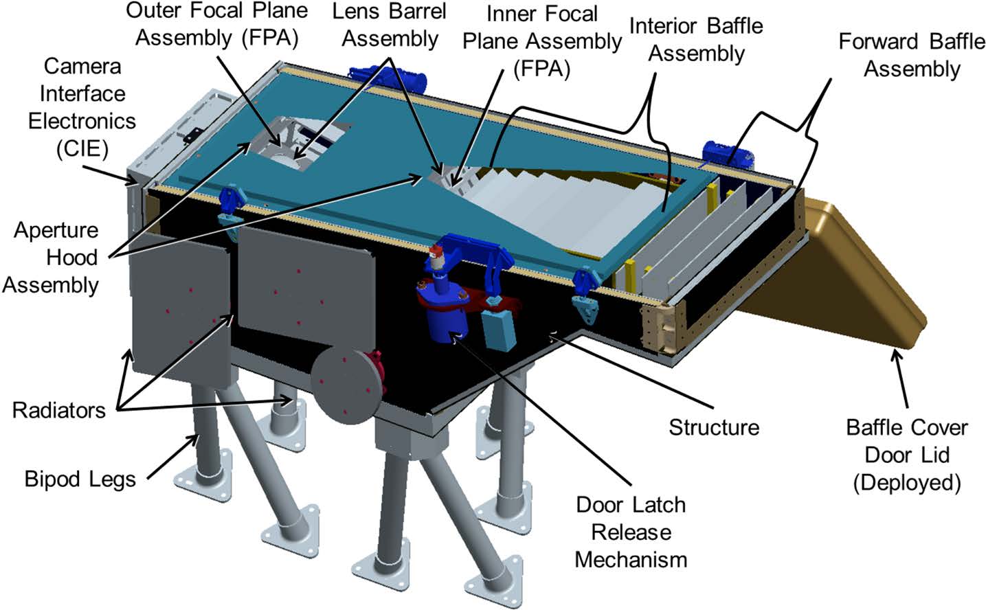
The WISPR Instrument Module (WIM) and its subassemblies. Two telescopes cover the WISPR FOV: the Inner and Outer telescope. Three baffle systems (Forward, Interior, and Aperture Hood) provide stray light control. The CIE controls the two APS detectors and is described in Sect. 3.3.1. The Door Latch release is the only WISPR mechanism. Most of the subassemblies are briefly described in Sect. 3
The WISPR design draws its heritage from the SECCHI heliospheric imagers aboard the Solar Terrestrial Earth Relations Observatory (STEREO; Kaiser et al. 2008) mission and from the SoloHI imager (Howard et al. 2013) under development for ESA’s Solar Orbiter mission scheduled for launch in 2017 (Müller et al. 2013). In fact, SoloHI provides many of the design elements and subsystems for adaptation into the WISPR design.
The WISPR instrument is being designed to live within a challenging set of science requirements and resource constraints. In order to achieve the necessary science, WISPR needs to take rapid sequences of images with highly variable signal content across an almost 90◦ FOV. To achieve this,WISPR uses a combination of baffle systems to greatly reduce incoming stray light, two optical systems to cover the large scene with uniform sensitivity, a novel low-powered radiation-hardened Active Pixel Sensor (APS) detector for each telescope, and an electronics chain with enough bandwidth to process images from both detectors and throttle the data down to meet spacecraft data transfer limits. The electronics and software are designed to meet the science requirements based on the conditions and environments predicted from 0.25 to 0.046 AU, while still allowing the flexibility to adapt to circumstances and observations beyond those requirements.
To optimize the science return of the mission, WISPR is located on the ram-side of the SPP spacecraft viewing the coronal structures to be encountered by the in-situ instrumentation (Fig. 8). This is also the reason that the radial FOV extends to 90 degrees elongation. This accommodation may expose the instrument to higher dust flux, during perihelion, than an anti-ram location but it is essential for providing the proper observations of the largescale structures that are being measured by the other SPP instruments, including the sources for any energetic particle events. Efforts are under way to understand and minimize the risk to the instrument from the inner corona environment as we discuss in Sect. 2.4. The adoption of a two-telescope design is driven by the need to accommodate the FIELDS antennas (Bale et al. 2014, this issue), which are located in front of WISPR, just behind the heat shield. With a single wide-angle lens system, two of the antennas would intrude into the unobstructed FOV of the lens leading to unacceptable stray light levels. Covering the WISPR FOV with two lens systems allows a more efficient masking of the reflections from these antennas and enables the safe operation of the instrument. This is discussed in more detail in the optical design section (Sect. 3.1).