System Description
The WISPR instrument comprises two modules: (1) the WISPR instrument module (WIM), shown in Fig. 9, includes the structure, baffles, door, telescopes, focal plane arrays (FPA) and the camera interface electronics (CIE), and (2) the Instrument Data Processing Unit (IDPU) which consists of the Data Processing Unit (DPU) and the Low Voltage Power Supply (LVPS). The electronics functional block diagram is shown in Fig. 10. TheWISPR Camera Interface Electronics (CIE) is an adaptation of the SoloHI electronics. The data is transferred from the WIM to the IDPU via a serial data interface similar to Camera Link, is compressed and packetized and is then transferred to the onboard Solid State Recorder via SpaceWire.
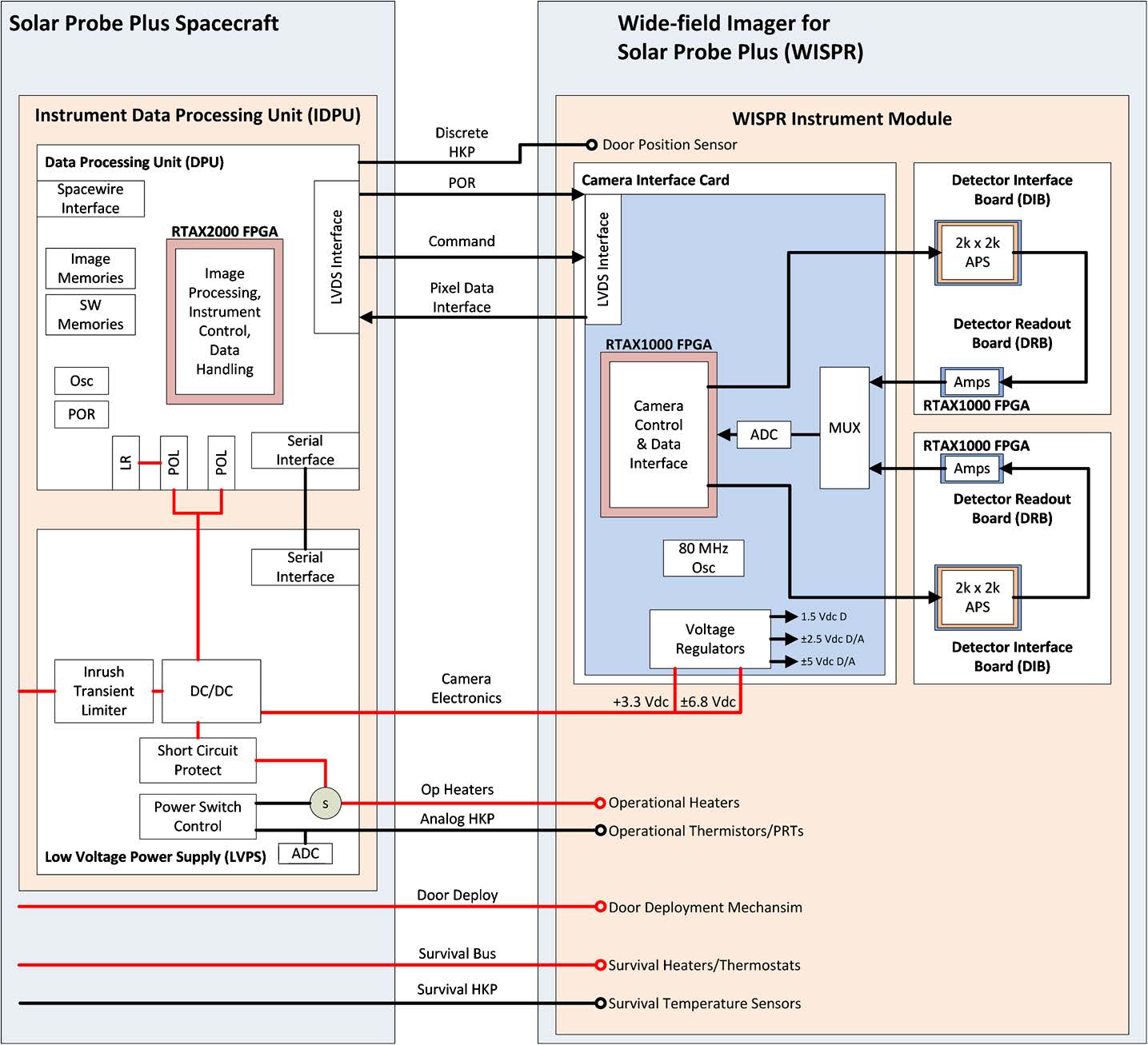
The IDPU controls the two cameras, the door deployment and the operational heaters, receives the analog data, digitizes it to 14 bits, removes cosmic rays, and adds individual images together to increase SNR. The IDPU is described in detail in Sects. 3.4–3.4.2. The WISPR instrument concept is in effect a miniaturization of the SECCHI/HI concept with adaptations from the SoloHI design. The WISPR telescope volume (54.3 (L) °ø 21.7 (W) °ø 26 (H) cm) is about 2.5 times smaller than the SECCHI/HI volume (72 (L) °ø 42 (W) °ø 24 (H) cm). It is the smallest Heliospheric Imager to date with capabilities that meet or even exceed the performance of the SECCHI/HI. It is a two-telescope system, similar to SECCHI/HI, with an inner telescope extending from 13.5◦ to 53◦ and an outer telescope extending from 50◦ to 108◦ (Fig. 9). The instrument uses the spacecraft heat shield as the first occulter and hence the alignment between the heat shield and the first occulter baffle, F1 is a critical element for the successful control of the stray light (see Sect. 3.1). The inner FOV cutoff is set at an elongation of 13.5◦ from Sun center, corresponding to a heliocentric distance of 2.3 Rs at 9.86 Rs perihelion. The cutoff is dictated by two requirements: (1) to remain within the heat shield umbra (8◦, including a 2◦ maximum spacecraft offpoint), and (2) to accommodate the instrument on the spacecraft bus at a reasonable height and with reasonable mass. The overall instrument characteristics are shown in the table below.
WISPR Instrument Characteristics
| Telescope Type | Wide-angle lenses, aperture stop placed in front of lens: Inner: f = 28 mm, aperture = 42 mm2, 490–740 nm (bandpass) Outer: f = 19.8 mm, aperture = 51 mm2, 475–725 nm (bandpass) |
|---|---|
| Plate Scale | 1.2–1.7 arcmin/pixel (inner-outer) |
| FOV | 95◦ radial × 58◦ transverse, inner field limit 13.5◦ from Sun center |
| Image Quality | Predicted RMS spot including allowable tolerances at 20◦ from boresight: Inner: 19.5 microns (2.34 arcmin) Outer: 19.9 microns (3.38 arcmin) |
| Detector | APS, 10 micron pitch, 2048 ×1920 pixels |
| Baffle Design/Stray Light Rejection |
Front heat shield edge, forward baffle and diffraction light trap designed to reject incoming solar radiation, interior baffles and aperture enclosures designed to reject scattered solar radiation from spacecraft structures, and thermal radiation from antennas. Average predicted stray light: <2×10⁻⁹ B/Bs @ 9.86 Rs and <2×10⁻¹² B/Bsun @ 0.25 AU, well below the K +F corona |
| Pointing | Instrument axes aligned to spacecraft to <0.5 deg, F1 and heat shield leading edge placement error <13 mm. Baffles achieve adequate rejection with 2◦ excursion from sun center at perihelion |
| Calibration | <20 % absolute radiometric, platescale <4 %, pointing: accuracy 5 arcmin (3σ), jitter 0.8 arcmin (1σ), windowed stability 1.6 arcmin (1σ) |
| Mass | WISPR Instrument Module (WIM) 9.8 kg; Instrument DPU (spacecraft provided) 1.1 kg |
| Average Power | 7 W (including 4 W operational heater power) |
| Envelope | WIM Module: 58 cm × 30 cm × 46 cm (door closed) |
| Avg TLM Rate | Allocated data rate 26.6 kbps (during 10-day operational periods); 23 Gbits per orbit |
A set of forward occulters (Forward Baffle Assembly) is located on a ledge to reduce the diffraction from the heat shield. An internal baffle assembly reduces this stray light component further as well as stray light diffracted from the FIELDS radio antennas and other spacecraft structures. Another set of baffles is located at the apertures of the two telescopes to prevent any further reflections from reaching the detectors. Because of the orbit profile, the WISPR stray light rejection requirements vary as a function of elongation angle and heliocentric distance by about an order of magnitude. The most stringent requirement is 1.8°ø10−12 B/Bsun at the outer edge of the FOV (90◦ elongation) at the largest distance from the Sun (0.25 AU). The sophisticated baffle design allows WISPR to meet this requirement and allows for high signal-to-noise ratio (SNR) imaging ranging from SNR = 20 at the inner FOV at closest perihelion to SNR = 5 at the largest distance and FOV angles. The detectors are 2048 °ø 1920 format APS CMOS devices developed for the SoloHI program (Howard et al. 2013). APS devices are much less susceptible to radiation damage than the more common CCD devices and are therefore the best option for this mission. They also come with significant savings in terms of power and mass. These devices are described in more detail in Korendyke et al. (2013). The devices are cooled to −60 ◦C via a passive radiator. A one-shot door protects the baffles and optics from contamination during ground operations, launch, and early flight operations.