Optical Design
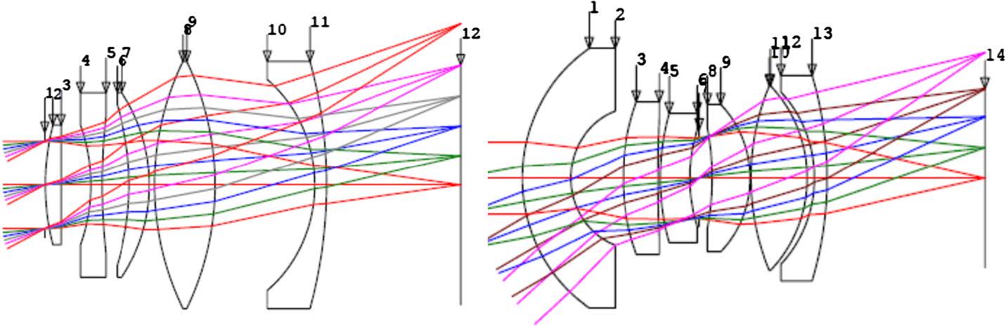
The instrument’s telescope design is monolithic (with no moving parts) and uses radiationtolerant glass lenses mounted in lens barrels. It is based on the SECCHI/HI design and consists of two telescopes, the inner and outer telescopes with the optical parameters shown in the table below. The optical layout is shown in the figure below (right side). The resolution is optimized for the FOV center, 33.5◦ and 79◦, for the inner and outer telescope, respectively. BK7 was selected for the first lens element because it was shown to be sufficiently resistant to dust impacts. The bandpass for each telescope is selected using a combination of long/short wavelength cutoff filters deposited on internal lens surfaces similar to SECCHI/HI.
|
|
As can be seen from the table below, the current optical design is excellent. It provides both fast lenses (low F#) and high spatial resolution (∼2 pixels) for the inner and outer telescopes, respectively. This means that WISPR is potentially capable of capturing images at spatial resolutions of <2 arcmin (2200 km or ∼3 arcsec from 1 AU), which are comparable to eclipse imaging from Earth. This is truly remarkable for a wide-field coronal telescope and the capability will be exploited as mission and solar condition allow. However, the current observing plan is to obtain images with 2°ø2 binning, as is done for SECCHI/HI, to increase the SNR and reduce the telemetry load. Higher image binning (4 °ø 4) will be required at large heliocentric distances to maintain a minimum SNR of 5 at the outer edge of the FOV.
WISPR Optical Design
| Telescope | FOV | Spectral Range (nm) |
Entrance Pupil (mm) |
F# | # of lenses | RMS Spot Size (μm) |
|---|---|---|---|---|---|---|
| Inner | 40◦ × 40◦ | 490–740 | 7.31 | 3.83 | 5-element | 19 |
| Outer | 58◦ × 58◦ | 475–725 | 8.08 | 4.04 | 6-element | 20 |
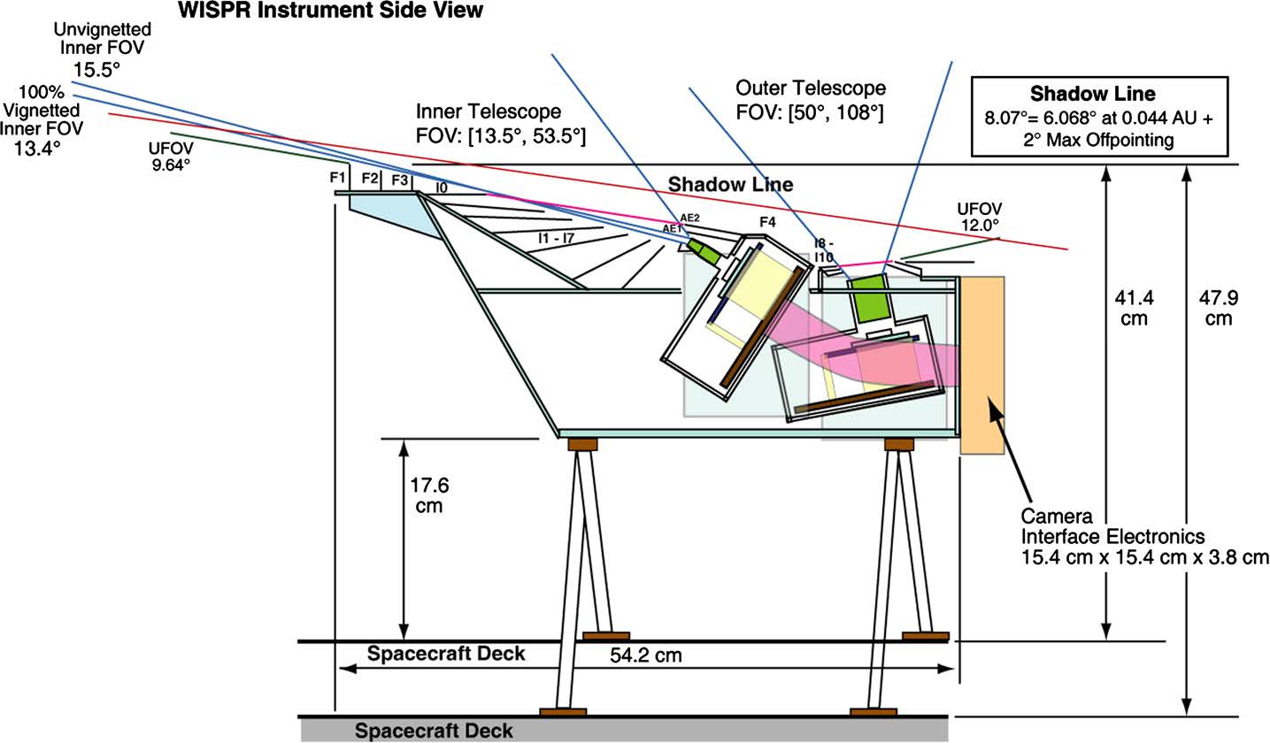
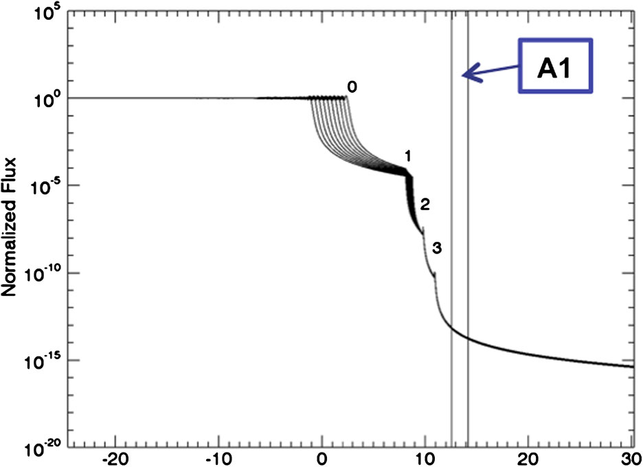
The baffle design rejects the incident solar radiation using a combination of the heat shield leading edge, front baffle assembly, and aperture light traps. Scattered radiation from the spacecraft is eliminated using the interior and peripheral baffle assemblies. The WISPR baffle design is based on the successful SECCHI/HI instrument design (Socker et al. 2000). The combination of the heat shield leading edge and the series of three linear occulters in the front baffle assembly attenuate the stray light that reaches the entrance aperture. Figure 16 shows the inner telescope normalized irradiance of the diffracted light from the heat shield/front baffle assembly combination at the worst off-pointing case of 2◦ during science operations at the minimum perihelion of 9.86 Rs. The worst-case diffracted stray light on the detector is predicted to be 7.5e-13 B/Bsun, which increases to 1.4e-11 B/Bsun when all the other sources of stray light are accounted for (dust damage on the first lens, F-corona, and scattering from the two FIELDS antennas). This is still 55 times lower than the requirement of 7.9e-10 B/Bsun. To deal with the sharp brightness gradient of the corona close to the limb, the last baffle (F3) in the forward baffle assembly imposes some vignetting of the innermost part of the Inner Telescope FOV from 60 % at 13.5◦ to 30 % at 14◦. Also, the wide-field lens creates natural vignetting (increasing as cos4 of the angle from the boresight).
The aperture light trap, including baffles AE1 and AE2, closes out the aft side of the entrance aperture and defines the aft Unobstructed Field Of View (UFOV) angle. The aperture light trap captures diffracted light from the F1 and F2 baffles, but does not directly intercept any diffracted light from the heat shield leading edge. The aperture light trap baffles are oriented toward the forward baffles such that no single reflection from the light trap directly enters the A1 aperture. The peripheral baffles limit stray light from surrounding spacecraft surfaces entering the interior baffle cavity. Following STEREO/HI, the interior baffles are CFRP panels coated with Aeroglaze Z307 to attenuate reflected stray light in the instrument. In addition, the interior baffles are oriented to prevent any single reflection of scattered light from spacecraft surfaces outside the aft UFOV from reaching the A1 aperture. The instrument is designed to remain below the direct solar radiation that comes over the heat shield leading edge from the sun disk edge throughout the entire PSP orbit for the worst-case off pointing. The shadow line in Fig. 15 defines this 8.07◦ solar exclusion zone based on the solar disk radius of 6.07◦ at the minimum perihelion of 9.5 Rs, the maximum failure mode off pointing of 2.0◦.
The baffle design directly drives the instrument volume. The design uses realistic baffle tolerances (e.g. 80 μm Z/220 μm X for F2/F3 baffles to F1 baffle; heat shield leading edge to F1 baffle tolerance given in Table 3 WISPR Instrument Characteristics) based on SECCHI/ HI and SoloHI experience. In addition, the instrument design includes a forward UFOV angle from the F1 baffle of 9.12◦ to avoid the heat shield leading edge for the worst-case tolerances. Overall, the current optical design meets the stray light requirements, even in the worst-case configurations of the FIELDS antennas and dust impacts.
Instrument Stray Light Control
 |
|
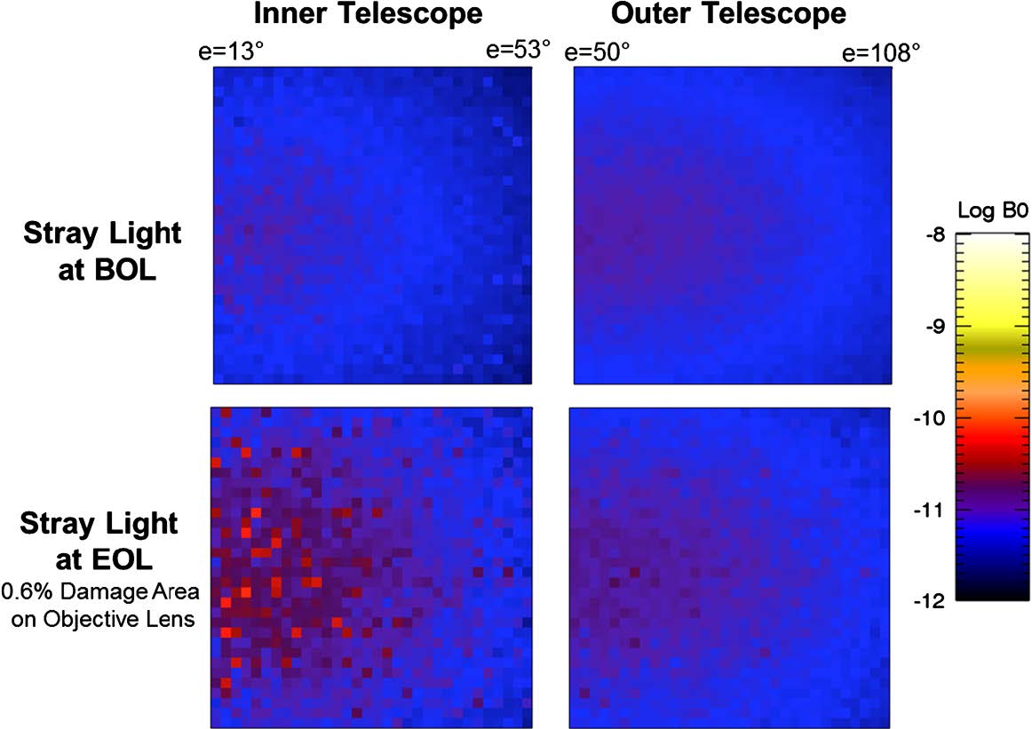
The control of stray light due to spacecraft accommodations has been the major focus of the WISPR team during the preliminary design phase of the project. The WISPR imager concept was a single wide-field lens, requiring an UFOV of 180◦. However, the FIELDS instrument needed to place its antennas on the sunward side of the spacecraft to sample the solar wind undistorted by the spacecraft charging effects. As a result, two of the antennas impinged either directly into theWISPR FOV or extended into the UFOV allowing diffracted sunlight to enter the aperture at unacceptable levels. In addition, the tips of the antennas will get so hot (∼1800 ◦C) that they will radiate in the visible region of the spectrum creating another (and novel) source of stray light. The only solution for allowing the instrument to operate was to baffle directly these two sources of stray light. In order to achieve this without sacrificing most of its FOV, theWISPR field-of-view was split into two separate imaging assemblies as discussed above.
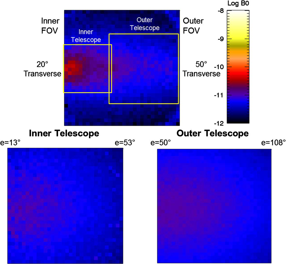
This change allowed the design of peripheral baffles that capture the diffracted and radiated light from the antennas and reduce the stray light to acceptable levels as shown in Fig. 17. This is a preliminary result, however. The stray light modeling is performed via Monte-Carlo techniques with the FRED Optical Engineering software using a CAD model of the instrument and FIELDS antennas. This approach allows not only the modeling of the antenna diffracted and radiated light but also the testing of various coatings for the baffle surface and even the modeling of the effects of dust impacts during the mission as we see in Sect. 2.4. These new stray light modeling methods, driven by the need to accommodate occulting-like imagers in crowded spacecraft environments, far exceed the corresponding modeling efforts in past coronagraphs and imagers where tight controls of structure intrusions in the UFOVs were possible. They demonstrate that visible light imagers can be accommodated and operate safely even when structures intrude into their direct UFOVs.