Mechanical Design
The WIM consists of a primary structure made from composite face sheets with a honeycomb core, which encloses two Focal Plane Assembly (FPAs) boxes, holding the detectors and detector readout boards (DRBs), two boxes for the baffles (interior and forward) and a plate for the peripheral baffle. In addition, the CIE is contained in a box attached to the rear of the primary structure and the radiators are mounted to the right side. The door mounts to the top and opens to the left.

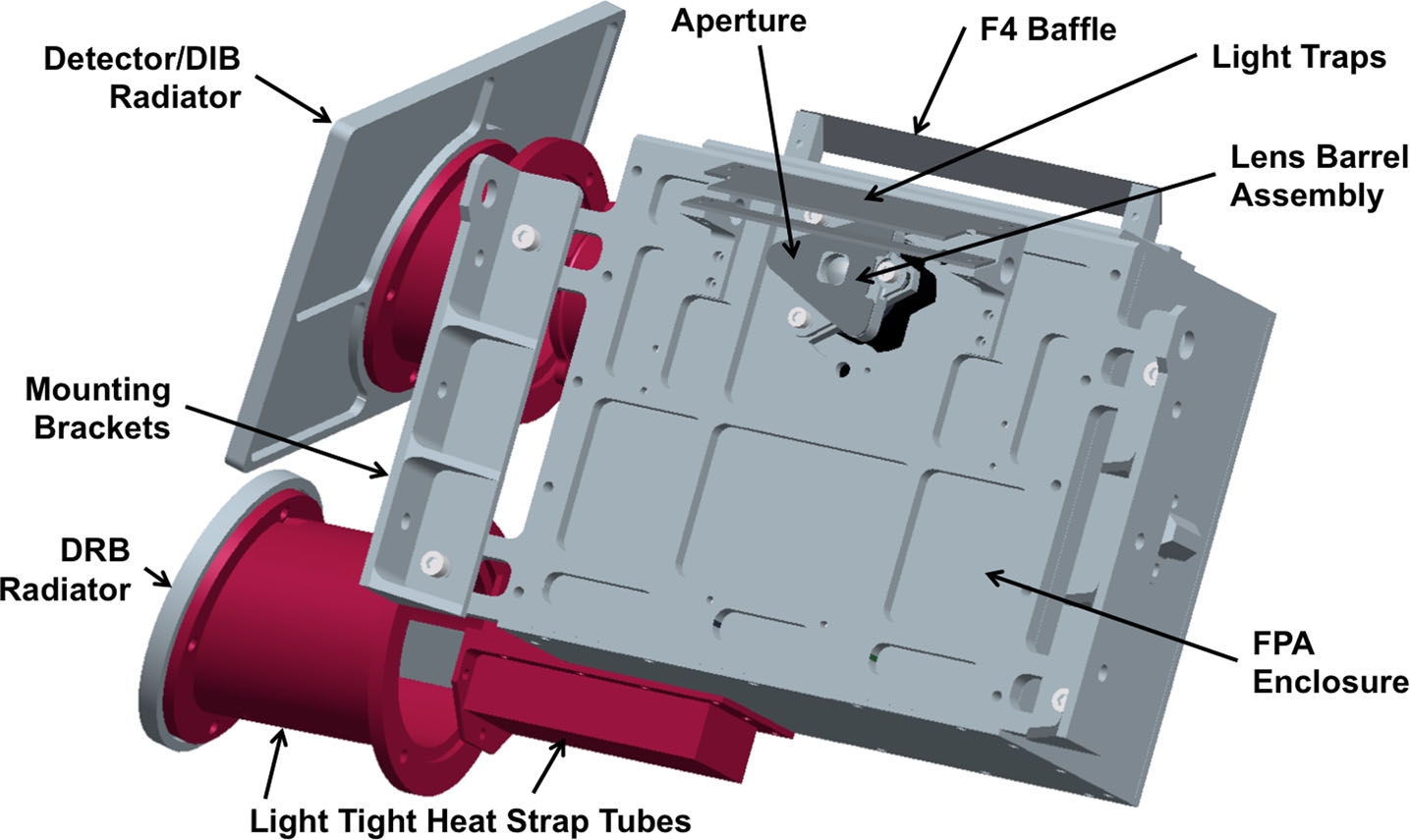
Focal Plane Assembly (FPA) The FPA provides physical mounting, optical positioning, electrical connections, and thermal cooling for the APS detector (Fig. 18). TheWISPR FPA design is a slight modification to the SoloHI FPA to account for the smaller detector, the APS control electronics, a warmer operating temperature, and a shorter distance to the radiator plate. The APS detector is cooled passively by conducting heat through a cold finger to a radiator with a view to deep space. A 10 ◦C temperature drop between the radiator and the detector is expected based on the SECCHI/COR2 performance. No difficulties are expected on obtaining temperature <−55 ◦C since the SECCHI/COR2 CCD is operating at <−70 ◦C.
Baffles
The mechanical design incorporates three baffle systems (forward, interior, and peripheral), all of them made of Al 6061. The forward baffles are attached to the truss structure with a series of clips and include shims for individual baffle alignment. The clips and screws are located on the outside edge of the baffles well outside the FOV. The interior baffles are assembled as a unit, which is then is mounted in the interior of the primary structure via pivot mounts on the sides and a mounting flexure in the front with shimming capability. The function of the peripheral baffle is to prevent stray light from the FIELDS antennas entering into the instrument. It is basically an Al plate with cutouts around the two telescope apertures. Those cutouts define the FOV of the instrument.
Door
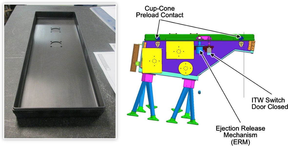
The one-shot WISPR door is a slight modification of the SoloHI door (Fig. 19). It is composed of several CFRP layers. The door blank is made using an invar mold for coefficient of thermal expansion (CTE) matching. It is mounted on the primary structures via two hinges. The Ejection Release Mechanism (ERM) is the sole WISPR mechanism (Fig. 19, right). It is a shape memory release device with a redundant firing circuit.
Instrument Mounts
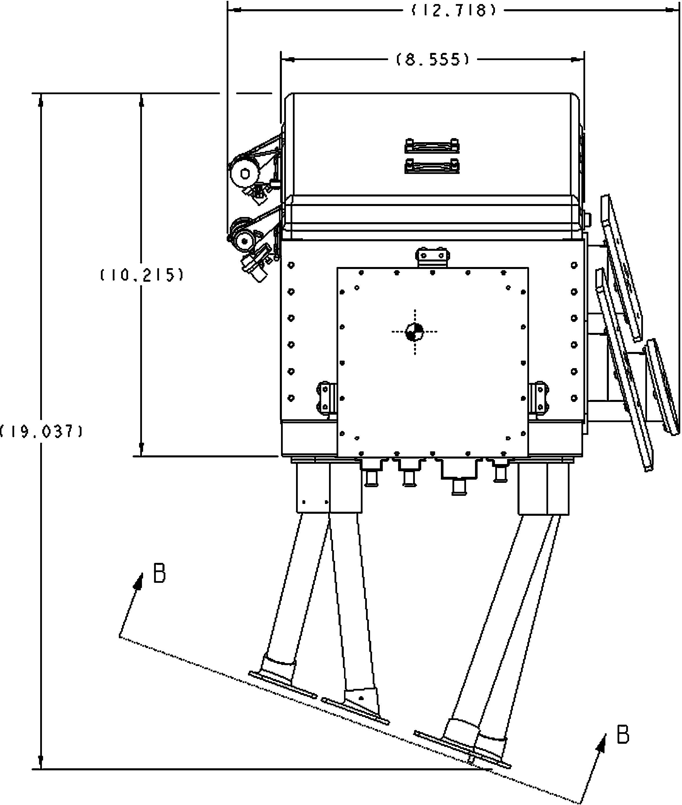
WISPR is mounted on the +X, +Y (ram-side) panel of the PSP spacecraft with four bipod mounts (Fig. 20). The PSP spacecraft is a hexagonal design and hence there is no panel facing directly towards the ram direction. WISPR is rotated by −20◦ about the Z relative to the panel to optimize the coverage of structures to be encountered by the spacecraft. The somewhat unconventional adoption of two legs per mount (hence bipod) provides the necessary stability. The composite (Ti-Al) tube mounts keep the instrument primary structural frequency >80 Hz, address CTE mismatch between panel and instrument, and maintain the instrument to spacecraft alignment.


